 kasploosh.com
Internal Electrical Outlets And Switches
2012-06-19
This page describes the simple electrical system that is built into the cabinet.
Design Requirements
I wanted the cabinet to have its own smart power system. The opposite of smart, to me, was a stereo cabinet with lots of wires sticking out the back, and having to reach around back to switch off a power strip. The following are the requirements for the design.
One Tail
This cabinet can roll around a room, but only if you minimize its connections out to rest of the world. If you have a stereo cabinet where each component's cord exits the cabinet and plugs into a wall, you have a solution that is not at all mobile.
I wanted the cabinet to have one single tail that leaves the cabinet and connects to the house’s power system. I used a long cord from an old power strip, since it has the right capacity, a molded plug, and stranded wire.
Two Power Sources
I wanted to have two power sources inside the cabinet, since there were going to be two kinds of equipment (computer and stereo) in two bays (left and right). If each side had its own power, then each side could be used independently of the other.
External Switches
The equipment that is stored in this cabinet is the kind that uses phantom power when not in use, and it was part of the design to be able to turn everything off. You could accomplish this by putting a surge protector with a switch inside the cabinet.
The problem with that approach is you would have to open the cabinet to turn off the cabinet, making it a more annoying job. Furthermore, the logical place for power is at the back of the cabinet. If you have to open the cabinet, kneel, and reach to the back, you will be super-annoyed.
You could bring the surge protector to the front of the cabinet, but then you have your fat power cords up front where they don't belong.
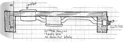
The outlet is inside the cabinet at the back, and
the switches are outside the cabinet at the front
The solution was to put the power switches on the outside of the cabinet. The diagram at right shows my idea for accomplishing the external switches, using the space under the cabinet floor for wiring.
Illuminated Toggle Switches
I wanted the toggle switches to be illuminated, because that is such a good reminder that you need to turn them off. We turn the cabinet off religiously, to make the green lights go away.
You don't have to do anything special to use illuminated toggle switches, other than purchase the right ones. But I did have to create a custom switchplate.
Circuit Design
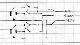
Circuit Diagram
The requirements for the circuit were what I already spelled out: one tail to the outside world, two independent channels of power inside the cabinet, switches on the outside of the cabinet to control each channel, and illuminated toggle switches.
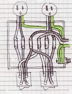
Wire routing to accomplish the circuit
The circuit diagram shows the design at its most basic, but things get more complicated when you want the switches at the front, the outlets at the back, and the tail in the middle. For that reason, the diagram of how the wires would actually be routed is more important.
Building It
The photo below shows an early version of the wiring. Since the time of that photo, the SPST switches have been replaced with DPST switches. Also, a cover was installed over the whole system, to protect it from dust and pets.
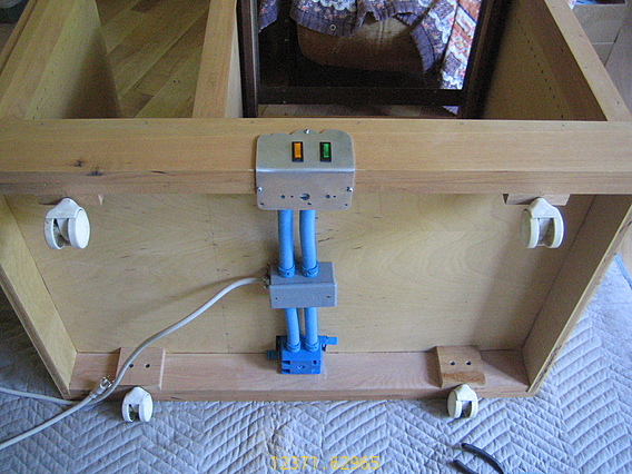
Electrical system. The SPST switches were changed to DPST. The casters shown here were temporary.