 kasploosh.com
More Wiring Options
2013-12-05
The previous pages dealt with the switches that provide many different ways to connect the pickups. After the switching section, there is a very normal output section.
The output section consists of:
- No tone control
- Master kill switch
- Master volume
- Output jack
- Diode clipping circuit
No Tone Control
Many guitars have a tone knob, but this one does not. This project gets different tones from the various ways of connecting the pickups. Adding a tone control was not a high priority.
Master Kill Switch
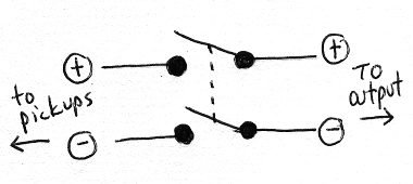
Basic kill switch
The three pickup switches give lots of different ways to connect the pickups, but one thing they do not provide is a quiet position. For this I needed a master kill switch, to completely disconnect the pickups. Plus, a kill switch is just fun to have.
I used a mini enclosed toggle switch with a full-size bat. I only needed DPST function, but used a DPDT switch because that’s what was available.
Master Volume

Basic volume control
In order to keep things relatively simple, I opted for a single volume switch to turn down the volume of the whole guitar. I had read about using a double variable resistor, to prevent the sound changing as the volume is turned down, but I opted not to go this route (partly because of the pots I wanted to use).
I used the Bourns 95 “Premium Guitar Pots”. These are specifically made for guitar applications, though I’m not sure what exactly is different. These are sealed pots with long life, and I used 500k. They are also smaller than old style open frame pots.
Output Jack
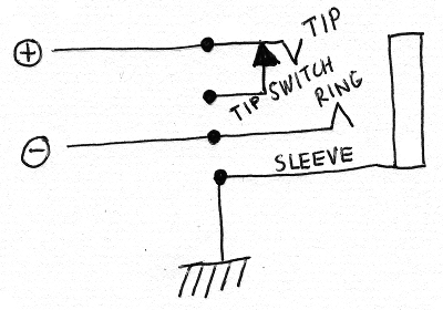
Used a TRS jack and connected negative to the ring
I did a couple of weird things at the output jack. Let me restate that I’m no expert!
The first thing I did that is maybe not normal is I carried the (what I’m calling) positive and negative wires all the way from the pickups to the output jack. The negative line was not connected to the chassis ground all along the way. Instead I used a TRS output jack, and connected positive to the tip and negative to the ring.
The reason that I carried the positive and negative all the way back to the jack is because I was reading this article about balanced guitar wiring. I don’t currently use balanced connections or equipment, but I left some room to experiment in the future.
Whenever I plug in a mono guitar cable, the shaft of the plug connects the ring and sleeve together, and basic mono function is maintained.
The second weird thing I did is use the tip switch of the jack to connect a diode clipping circuit that is only in effect when the plug is inserted to the first click (see below).
Diode Clipping Circuit
Maybe you have heard of “Black Ice”, a passive clipping circuit that is sold as an epoxy filled cube. The fact that the device is small, passive, and obscured made me wonder what could be inside. Something simple?
Talk on the internet suggested that the clipping was mainly done by diodes in opposite directions, connecting signal to ground. The diodes “turn on” at a certain signal level, and anything above that level is neutralized. This gives your waveforms plateaus at the top, and therefore a clipped sound. The pair of diodes is needed so that the clipping works on both halves of the waveform.
The clipping that is achieved is passive, so it only subtracts from your sound. And you have to have fairly hot pickups to have a signal high enough to trigger the diodes. And the diodes need to work at low voltages found on the guitar.
Several people mentioned Schottky diodes, because they work at low voltages, and react quickly.
Working With Surface Mount Diodes
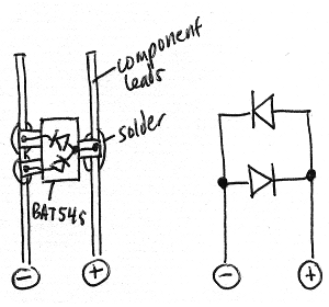
If not using a capacitor...
Use some component leads to support the BAT54S
I wound up getting BAT54S Schottky diodes. The BAT54S is a package that includes two opposing diodes. The ones I got were tiny, like a grain of rice, because they were for surface mount applications. They were hard to work with.
If not using a capacitor...
Resulting schematic
But I did get the BAT54S soldered up. The trick is to first solder them on to sturdier legs; I used leads that were clipped off some other component. Once the BAT54S is soldered to the leads, you can use it like you would any component.
Capacitor Or Not?
If using a capacitor...
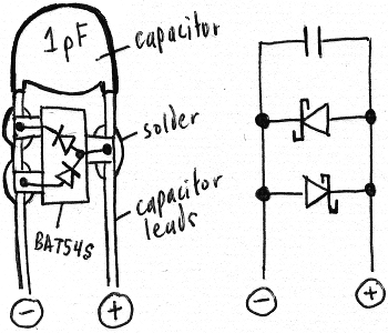
Using the leads of the cap to support the BAT54S
I can’t remember if I used a capacitor as part of the clipping circuit or not! It was a busy day. I will know the answer to this the next time I take the guitar apart. If I did use a capacitor, it would be according to the illustrations in this section.
A capacitor that is in parallel with the clipping diodes can be seen in, for example, TS-808 Tube Screamer schematic drawings. I read some commentary that the capacitor works to soften the clipping a little.
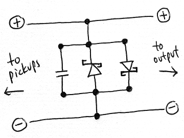
If using a capacitor...
Resulting schematic
I was interested in this partly so I could use the legs of the capacitor to support the BAT54S. If I used this approach, I probably used a very low capacitor value, like 1pF, so that any effect would be minimal. The capacitor value in the TS-808 schematic I saw was 51pF.
And if I did this, I surely used an inexpensive ceramic capacitor. I wanted a very low value, and it was all just an experiment anyway.
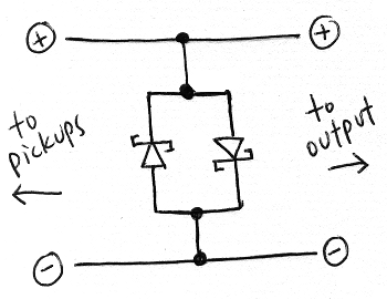
Attaching The Clipping Circuit
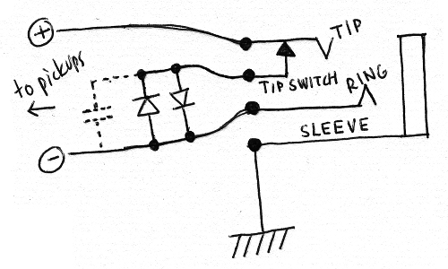
The clipping circuit connected to the tip switch on the jack
Not sure if I used a capacitor (shown dashed)
But where could I put this clipping circuit? I did not want to add yet another switch to the guitar. Then I had an idea. I attached one leg of the clipping circuit to the negative line at the jack. I attached the other leg to the tip switch of the jack.
What this means is that the clipping circuit is engaged when the plug is inserted to the first click. When the plug is inserted all the way, the clipping circuit is disengaged.
In other words, I can use the clipping circuit by pulling the cord plug out halfway. It’s like an easter egg for the guitar, and it is fun to play around with.
How Does It Sound?
I made little drawings of the clipping circuit, but drawings don’t tell you how it sounds. Would I recommend other people do this?
No, I would not exactly recommend someone else do this. It does not sound high quality, or like an overdriven tube amp. It sounds like you are running your signal through some diodes, and that’s good enough for me. People who like lo-fi and weird sounds might like it too.